
Upgrading the IC-9700 for use on EME
An Evolution of Radios
Over the years we have used many transceivers for EME operations. We've always kept the transmit and receive separate out of caution for tower mounted preamps, etc. That required some radios, like the Kenwood TS-2000, to be modified to provide separate receive and transmit capabilities. Others, like the Yaesu FTDX-5000 and Elecraft K3S, provided separate transverter connections.
When we started using digital modes we found that the transverter that was in use was not stable enough even after adding a tcxo. Stability problems were solved by upgrading to Kuhne transverters with a GPS disciplined 10 MHz reference input. Both the NC1I 70cm and 23cm home stations are locked to a 10 MHz reference signal fed by a distribution amp. This includes the K3S which also has the (optional) reference input. Similarly, the DXpedition station used over the last few years likewise used components that were all GPS locked..
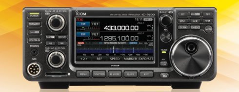
IC-9700
Our EME DXpeditions in the last decade started out with the Yaesu FTDX-5000. Great rig but overkill: way too big and heavy, and requires the use of transverters. The 5000 was replaced by an Elecraft K3S - super reduction in weight (especially without the internal amp in the K3) but still required transverters.
We recently noticed that the Icom IC-9700 is being used by a lot of moonbouncers and that seemed like a perfect fit for our next DXpedition radio: small, lightweight and includes 2m, 70cm, and 23cm.
This radio unfortunately has some shortcomings, including:
- Lack of reference oscillator input
- Lack of separate transmit and receive connections
Reference Oscillator Input
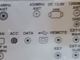
At first look the rig has a 10 MHz reference input. But when you dig deeper, this isn't your typical GPS locked 10 MHz input that is used to stabilize frequency - its only used for calibration purposes. Strange design ...
Thankfully there is a fairly simple solution: the Leo Bodnar IC-9700 Reference Injector Board which uses the REF IN 10 MHz connector to couple a signal directly to the rig through their board that mounts on standoffs using a couple of the PCB mounting positions - ingenious.
The reference frequency needs to be 49.152 MHz which means our existing 10 MHz source wouldn't do. Leo Bodnar has two GPS locked reference clock oscillators that will supply this frequency - we opted for the more expensive Leo Bodnar Precision GPS Reference Clock.
Setup is well documented on the Leo Bodnar web site: it only took a few minutes using their utility program and accessing the interface via its USB interface.
IC-9700 Separate Receive and Transmit
Unfortunately the IC-9700 lacks separate RX and TX connections, and like the TS-2000, is a fairly small package that doesn't provide much space to make or bring out additional connections.
NC1I and I spent some time looking over the radio and we came up with a brilliant idea: add a spacer between the fan and the cast body of the rig to accommodate separate receive connections.
The fan is a standard 80 x 80 mm size and is recessed 10 mm inside the rig's housing. The plastic fan housing is approximately 2 mm thick. The solution was simple, or so we thought: 80 x 80 mm square aluminum tubing - but in the US this kind of material is not readily available (though we found plenty of sources in Europe for it). We ended up having a local machine shop fabricate the spacer for us out of aluminum. The spacer is 30 mm deep which extended the fan 20 mm off the back of the rig allowing for plenty of space to provide three SMA style connections. Four new stainless pan head Philips screws M4 x 60 mm long (0.70 mm thread) were ordered to replace the existing fan mounting screws.
And Icom even helped us out: the fan wires are actually exceedingly long, so much so that Icom coils up the excess and ties it off inside the radio. There was plenty of cable to extend the fan without the need to modify the fan cable!
IC-9700 Photo Album
Please see the IC-9700 Modifications for images, including:
- view of the underside of the IC-9700 with the Leo Bodnar board (outlined in red) installed
- fan spacers - metric square aluminum should be easy to find in most countries
- installation of the fan spacer with connectors to show clearances
- we opted to provide three SMA connections on the top of the spacer